News CAST Announces CMI as Exclusive Distributor for BlackTrax in Australia and New Zealand Read More » August 1, 2024
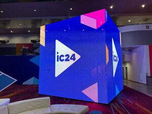
News CAST Group of Companies Shines at InfoComm 2024 with BlackTrax Technology Integration Read More » June 14, 2024